Views: 0 Author: Site Editor Publish Time: 2026-07-28 Origin: Site
Achieving precise, repeatable positioning often frustrates design engineers. You do not need to design custom detent mechanisms from scratch. Instead, component standardization offers a faster route. Standardized Spring Plungers solve this assembly problem instantly. They mitigate machinery wear and reduce assembly time significantly. They also standardise component ejection across production lines.
By using pre-assembled units, we eliminate unpredictable friction profiles. Engineers simply insert the component and immediately gain a reliable holding force. This engineering guide moves from basic mechanical principles to advanced technical specifications. You will learn how to evaluate, compare, and procure the exact component you need.
We will explore everything from lateral load limits to environmental compliance factors. We will also review installation best practices to prevent mechanical failures. Your tooling designs will become more reliable, and your production lines will run smoother. Dive into the mechanics below to optimize your next machinery build.
Standardization over customization: Spring loaded ball plungers eliminate the need for custom-machined detents, saving engineering time and manufacturing costs.
Application dictates type: Choosing between a ball spring plunger and a spring plunger pin depends entirely on lateral vs. vertical load requirements and expected cycle life.
Force matters: Correctly specifying initial and final end force is critical to preventing premature spring fatigue or component galling.
Material compliance: Evaluating body and tip materials (e.g., 316 stainless vs. Delrin) is essential for harsh environments and regulatory compliance.
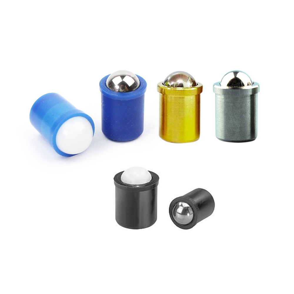
Modern manufacturing demands modular, predictable components. These small devices pack complex engineering into a tiny footprint. We call this an encapsulated design. A standard unit features a threaded outer body, an internal compressed spring, and a moving tip. The tip usually takes the form of a ball or a cylindrical pin. Manufacturers seal these internal parts tightly. This self-contained assembly acts as a single, functional mechanical unit.
Engineers previously wasted hours designing custom detents. They machined custom housings, sourced individual springs, and calculated separate tolerances. Today, spring loaded ball plungers solve this business problem directly. They streamline manufacturing significantly. They provide pre-calculated, highly reliable holding forces. Builders use them in complex fixtures, stamping dies, and movable machine parts. You simply look up the required force in a catalog and install the unit.
However, we must understand the operational reality of these components. Static holding differs greatly from dynamic indexing. Static holding keeps a dormant part in place. Dynamic indexing involves continuous, high-speed movement across the plunger face. Dynamic environments push cycle limits and accelerate mechanical wear over time. You must set realistic baseline expectations. A standard plunger might survive one million cycles under light loads. Heavy impacts will reduce that lifespan drastically.
Common Mistake: Designers often ignore side-loading forces on extended tips. Side-loading creates immense friction inside the body. It damages the internal spring and causes catastrophic failure. Always align the thrust vector parallel to the plunger travel path.
Friction profiles define component selection. A ball spring plunger utilizes rolling friction. The spherical tip rolls easily against mating surfaces. This makes them ideal for lateral thrusts and smooth detents. When a machine slide moves horizontally, the ball depresses smoothly. It does not scrape or gouge the moving part.
Conversely, a spring plunger pin relies on sliding friction. The cylindrical pin presents a flat or rounded face. Pins handle much heavier shear loads than balls. They excel at heavy-duty locating tasks and robust push-off functions. If you need to eject a heavy metal stamping from a die, you choose a pin. The pin offers greater surface area and superior structural rigidity.
Some applications require constant operator intervention. A retractable spring plunger features an external knob or pull-ring. Operators pull the knob to retract the internal pin manually. This action releases the workpiece instantly. Once the operator lets go, the spring snaps the pin back into place.
We see hand-retractable styles frequently on adjustable gym equipment and medical beds. They shine in scenarios requiring rapid, frequent adjustments. Furthermore, a spring loaded index plunger provides exact, rapid positioning on manufacturing jigs. You can lock a rotary table into precise degree increments effortlessly. Many indexing models include a locking notch. Operators pull and twist the knob to keep the pin fully retracted.
Installation methods dictate holding security. Threaded bodies provide maximum retention. They screw directly into tapped holes. They resist severe vibration and extreme pull-out forces. You can fine-tune their depth by turning the threaded body. This adjustability makes them highly versatile.
Press-fit variations offer a different advantage. They feature smooth outer bodies. Installers press them directly into un-tapped holes. This method drastically improves installation speed. It eliminates tapping operations entirely. We use push-fit variations primarily in softer housing materials. They work beautifully in aluminum, soft woods, and industrial plastics. However, they cannot handle heavy pull-out forces.
Mechanical Plunger Comparison Guide
Component Type | Primary Friction Mode | Ideal Application | Lateral Load Capacity |
|---|---|---|---|
Ball Style | Rolling Friction | Smooth detents, lateral movement | Low to Moderate |
Pin Style | Sliding Friction | Part ejection, solid locating | High |
Retractable Style | Manual Override | Adjustable fixtures, operator handles | Moderate |
Press-Fit Body | Static Friction | Soft housings, rapid assembly | Very Low (Pull-out) |
Calculating the correct spring pressure ensures mechanical reliability. We measure force at two specific points. Initial force describes the pressure when the tip rests uncompressed. Final force describes the pressure when the tip retracts completely. You must map these values against your application parameters.
Over-specifying force creates severe problems. Too much pressure leads to rapid user fatigue on manual adjustments. It also causes component galling on softer mating parts. Under-specifying force allows parts to rattle or shift during operation. If you need precise tactile feedback, a heavy-duty spring loaded spring plunger provides a distinct, crisp snap. Always consult the manufacturer force charts before finalizing your design.
Harsh environments destroy improper materials quickly. You must evaluate chemical exposure and ambient moisture. Material choices affect both performance and regulatory compliance.
Steel vs. Stainless Steel: Standard carbon steel provides excellent strength. However, it rusts quickly in humid environments. We specify 316 stainless steel for food processing or medical applications. Stainless steel resists corrosion and maintains strict RoHS compliance globally.
Delrin and Nylon Tips: Hardened steel tips mar softer materials. They will gouge finished plastics or extruded aluminum. Delrin or Nylon tips prevent this surface damage entirely. They offer natural lubricity and excellent wear resistance.
Specialty Bodies: Some aerospace applications demand ultra-lightweight components. In these rare cases, engineers might specify engineered polymer bodies.
Thread pitch impacts adjustment sensitivity. Coarse threads allow rapid installation. They drive deep into the housing quickly. Fine threads offer granular, micro-adjustments. They allow technicians to dial in the exact protrusion depth needed for high-precision tooling.
Manufacturer-provided tolerance data is non-negotiable. High-precision tooling requires exact concentricity. The plunger body must align perfectly with the internal spring path. Cheap components feature loose tolerances. This slop causes the tip to jam or bind under pressure. Always demand dimensional spec sheets from your supplier.
Vibration acts as an invisible enemy. It causes threaded fasteners to back out slowly. In high-vibration machinery, loose plungers destroy indexing accuracy. Nylon thread-locking patches provide an excellent solution. Manufacturers apply a Nylok patch directly onto the external threads.
This patch compresses during installation. It creates intense radial tension against the mating threads. It prevents the body from rotating under heavy machine vibration. If your application involves stamping presses or combustion engines, you must specify thread-locking features. It saves countless hours of reactive maintenance.
Even the best components fail under poor conditions. We must anticipate and mitigate common failure modes. Spring fatigue represents the most frequent issue. Springs lose their elasticity after millions of compressions. The internal coil snaps or sags permanently. You must adhere to the manufacturer cycle limits.
Tip galling occurs when two identical metals rub together under pressure. The metals microscopically weld and tear apart. You prevent galling by mixing materials or adding heavy lubrication. Thread stripping happens during clumsy installations. Machinists cross-thread the tiny bodies into misaligned holes. Finally, improper side-loading ruins standard pin styles. Lateral force bends the extended pin. It jams permanently inside the threaded shell.
Correct installation demands proper tooling. You cannot install these delicate assemblies with generic pliers. Pliers crush the outer threads instantly. Manufacturers design specific installation tools for these components.
You must use proper spanner wrenches or hex keys. Many models feature a hex socket built into the rear end. This allows simple insertion using a standard Allen key. However, you must observe strict torque limitations. Hollow-threaded bodies possess thin walls. Excessive torque stretches the metal. It deforms the internal bore and traps the moving pin. Always use a calibrated torque wrench during final assembly.
Real-world environments generate contamination. Metal shavings, dust, and cooling fluids attack the assembly. We must establish realistic maintenance assumptions for high-cycle environments.
Clearance of debris is critical. If metal chips fall into the spring cavity, the plunger locks solid. Regular compressed air blow-outs prevent this buildup. Lubrication extends cycle life significantly. A drop of light machine oil reduces internal friction. Eventually, you must replace the units entirely. High-cycle automated environments require scheduled replacement. Do not wait for a spring to snap before swapping the component.
Selecting the perfect component requires a systematic approach. Guesswork leads to engineering failures. Follow this strict shortlisting logic to guarantee success.
Define the primary function: You must classify the action accurately. Are you indexing a rotary table? Are you ejecting a hot plastic part from a mold? Are you simply locating a bracket temporarily? Ejection requires heavy pin force. Smooth indexing requires light ball rolling.
Map the environment: Analyze the operational surroundings completely. Document chemical exposure risks. Record extreme temperature fluctuations. Measure ambient vibration levels. High heat destroys internal plastic springs. Corrosive wash-downs mandate stainless steel construction.
Calculate the force requirement: You need concrete numbers. Weigh the mating part accurately. Determine the desired tactile feedback. Does the operator need a heavy click, or a soft glide? Calculate both the resting initial force and the fully compressed final force.
Request engineering assets: Never procure bulk units blindly. Request complete 3D CAD models from the supplier. Import these models into your digital assembly. Check for physical interferences. Request physical spec sheets and sample testing protocols. Test a small batch before authorizing mass production.
Standardized components drastically simplify complex machinery design. While spring plungers appear small, their proper specification prevents major downstream machinery failures. They eliminate custom machining, reduce assembly times, and standardize performance across global manufacturing facilities. You must understand the distinct differences between rolling friction balls and solid sliding pins.
Force dynamics and material selections dictate longevity in the field. Ignoring installation torque limits or side-loading restrictions guarantees premature failure. Always match the mechanical characteristics to your specific environmental demands. Take the next step in optimizing your mechanical assemblies today. Review the comprehensive product catalog. Download the exact 3D CAD files for your specific assembly geometry. Contact our technical support team to configure custom end-force parameters tailored perfectly to your production line.
A: A ball type uses a rolling sphere, making it ideal for lateral movements and smooth detents. A pin type uses a solid cylindrical tip. Pins handle direct-thrust applications and heavy shear loads, perfect for locating or ejecting heavy parts.
A: Force is measured at two distinct states. Initial force is the resting pressure when the tip is fully extended. Final force is the maximum pressure exerted when the spring is fully compressed inside the housing body.
A: Yes, but with strict limitations. Extended pins handle moderate shear loads, but excessive lateral force bends the pin. This side-loading creates internal friction, causing the retraction mechanism to jam or fail prematurely.
A: Yes. Manufacturers standardize these components globally. You can procure them in standard metric threads (like M6 or M8) and standard imperial dimensions to ensure seamless integration into any international manufacturing assembly.