


113.8 Ball Lock Pins with Plastic T handle
PDM
| Quantity: | |
|---|---|
Features of 113.8 Ball Lock Pins,Stainless Steel AISI 630,T Handle Plastic
The core advantage is high load-bearing capacity. Rated breaking load under double shear is clearly specified in technical datasheets. The pin remains firmly locked under heavy load and continuous vibration conditions to avoid unintended release.
Customization Service:
✅ Custom Length: Custom lengths available to match your installation space and working conditions.
✅ T-handle Customization: The T-handle can be customized in material, color and surface finish to meet special requirements such as anti-corrosion or anti-static.
T Handle Heavy Duty Ball Lock Pins Title:
Custom Quick Release Pin Manufacturer 40mm OEM Custom ISO Certified Quick Release Pin for Industry
Machinery Quick Release Ball Lock Pins Stainless Steel 304 420 630 T-Handle Quick Release Ball Lock Pins for Gym
Button Handle Ball Lock Pins 5/6/8/10/12mm polished passviated nickel plated quick release ball pins for Great Price
The Quick Release Ball Pins parameters are strictly executed in accordance with DIN industry standards, with independent and verifiable technical data to support customer project selection and bulk procurement:
| Item | Specification |
| Product Name | 113.8 Ball Lock Pins Stainless Steel with T Handle |
| Main Shank Material | AISI 630 (17-4PH) precipitation hardened stainless steel, high hardness and anti-fatigue |
| Ball Material | AISI 420C stainless steel, wear-resistant and impact-resistant |
| Spring Material | AISI 630 stainless steel, stable elastic recovery, long service life |
| Handle Material | Glass fiber reinforced PA polyamide plastic, insulated, anti-corrosion, temperature-resistant |
| Core Mechanical Property | Standard double shear breaking load (rated load), stable heavy-load bearing capacit |
| Machining Precision | CNC integral machining, shank tolerance -0.04/-0.08mm, length tolerance +0.6m |
| Surface Treatment | Passivation hardening treatment, enhanced surface wear resistance and oxidation resistanc |
| Structural Feature | Plastic T-handle one-touch operation, built-in self-locking ball, no auxiliary tools require |
| Certification | RoHS compliant, suitable for industrial standard assembly scenarios |
| Application | Heavy Duty,General Industry,Wheelchair,Gym Equipments,etc |
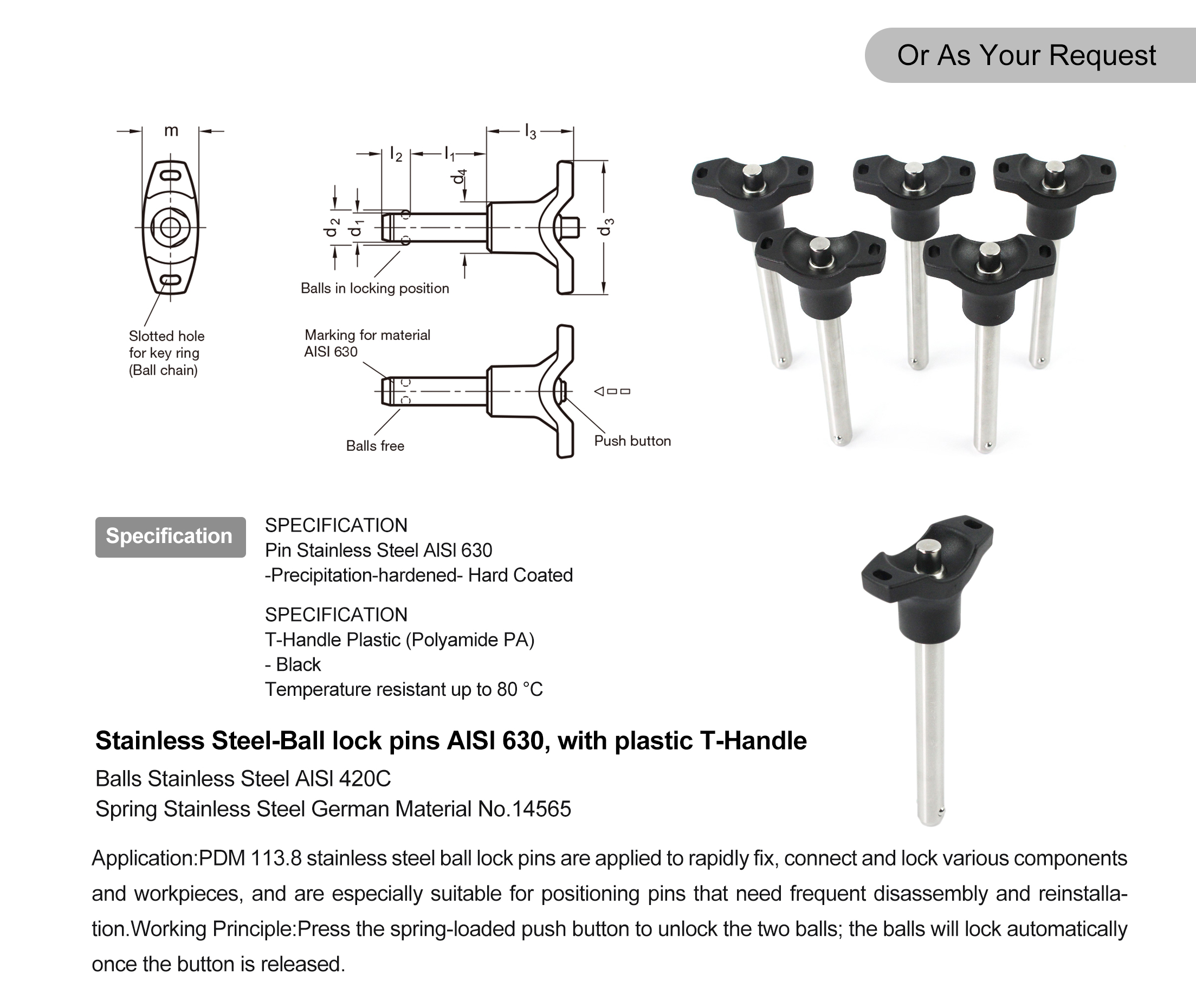
113.8 PA T handle Quick Release Ball Lock Pins
| PDM industry's safety lock pins | Stainless Steel | |||||||||
| Description | d1 | I1 | d2 | d3 | d4 | I2 | I3 | m | Locating Bore H11 | Load in KN=Double SidedShearing Resistance according DlN 50141(Breaking Strength) |
| -0.04/-0.08 | +0.6 | ±1 | ||||||||
| PDM 113.8-5-10 | 5 | 10 | 5.5 | 40 | 13.5 | 6 | 25 | 15.5 | 5 | 24 |
| PDM 113.8-5-15 | 5 | 15 | 5.5 | 40 | 13.5 | 6 | 25 | 15.5 | 5 | 24 |
| PDM 113.8-5-20 | 5 | 20 | 5.5 | 40 | 13.5 | 6 | 25 | 15.5 | 5 | 24 |
| PDM 113.8-5-25 | 5 | 25 | 5.5 | 40 | 13.5 | 6 | 25 | 15.5 | 5 | 24 |
| PDM 113.8-5-30 | 5 | 30 | 5.5 | 40 | 13.5 | 6 | 25 | 15.5 | 5 | 24 |
| PDM 113.8-5-35 | 5 | 35 | 5.5 | 40 | 13.5 | 6 | 25 | 15.5 | 5 | 24 |
| PDM 113.8-5-40 | 5 | 40 | 5.5 | 40 | 13.5 | 6 | 25 | 15.5 | 5 | 24 |
| PDM 113.8-5-45 | 5 | 45 | 5.5 | 40 | 13.5 | 6 | 25 | 15.5 | 5 | 24 |
| PDM 113.8-5-50 | 5 | 50 | 5.5 | 40 | 13.5 | 6 | 25 | 15.5 | 5 | 24 |
| PDM 113.8-5-60 | 5 | 60 | 5.5 | 40 | 13.5 | 6 | 25 | 15.5 | 5 | 24 |
| PDM 113.8-5-70 | 5 | 70 | 5.5 | 40 | 13.5 | 6 | 25 | 15.5 | 5 | 24 |
| PDM 113.8-5-80 | 5 | 80 | 5.5 | 40 | 13.5 | 6 | 25 | 15.5 | 5 | 24 |
| PDM 113.8-6-10 | 6 | 10 | 7 | 40 | 13.5 | 7.1 | 25 | 15.5 | 6 | 35 |
| PDM 113.8-6-15 | 6 | 15 | 7 | 40 | 13.5 | 7.1 | 25 | 15.5 | 6 | 35 |
| PDM 113.8-6-20 | 6 | 20 | 7 | 40 | 13.5 | 7.1 | 25 | 15.5 | 6 | 35 |
| PDM 113.8-6-25 | 6 | 25 | 7 | 40 | 13.5 | 7.1 | 25 | 15.5 | 6 | 35 |
| PDM 113.8-6-30 | 6 | 30 | 7 | 40 | 13.5 | 7.1 | 25 | 15.5 | 6 | 35 |
| PDM 113.8-6-35 | 6 | 35 | 7 | 40 | 13.5 | 7.1 | 25 | 15.5 | 6 | 35 |
| PDM 113.8-6-40 | 6 | 40 | 7 | 40 | 13.5 | 7.1 | 25 | 15.5 | 6 | 35 |
| PDM 113.8-6-45 | 6 | 45 | 7 | 40 | 13.5 | 7.1 | 25 | 15.5 | 6 | 35 |
| PDM 113.8-6-50 | 6 | 50 | 7 | 40 | 13.5 | 7.1 | 25 | 15.5 | 6 | 35 |
| PDM 113.8-6-60 | 6 | 60 | 7 | 40 | 13.5 | 7.1 | 25 | 15.5 | 6 | 35 |
| PDM 113.8-6-70 | 6 | 70 | 7 | 40 | 13.5 | 7.1 | 25 | 15.5 | 6 | 35 |
| PDM 113.8-6-80 | 6 | 80 | 7 | 40 | 13.5 | 7.1 | 25 | 15.5 | 6 | 35 |
| PDM 113.8-8-10 | 8 | 10 | 9.5 | 48 | 18 | 8.2 | 31 | 20.5 | 8 | 63 |
| PDM 113.8-8-15 | 8 | 15 | 9.5 | 48 | 18 | 8.2 | 31 | 20.5 | 8 | 63 |
| PDM 113.8-8-20 | 8 | 20 | 9.5 | 48 | 18 | 8.2 | 31 | 20.5 | 8 | 63 |
| PDM 113.8-8-25 | 8 | 25 | 9.5 | 48 | 18 | 8.2 | 31 | 20.5 | 8 | 63 |
| PDM 113.8-8-30 | 8 | 30 | 9.5 | 48 | 18 | 8.2 | 31 | 20.5 | 8 | 63 |
| PDM 113.8-8-35 | 8 | 35 | 9.5 | 48 | 18 | 8.2 | 31 | 20.5 | 8 | 63 |
| PDM 113.8-8-40 | 8 | 40 | 9.5 | 48 | 18 | 8.2 | 31 | 20.5 | 8 | 63 |
| PDM 113.8-8-45 | 8 | 45 | 9.5 | 48 | 18 | 8.2 | 31 | 20.5 | 8 | 63 |
| PDM 113.8-8-50 | 8 | 50 | 9.5 | 48 | 18 | 8.2 | 31 | 20.5 | 8 | 63 |
| PDM 113.8-8-60 | 8 | 60 | 9.5 | 48 | 18 | 8.2 | 31 | 20.5 | 8 | 63 |
| PDM 113.8-8-70 | 8 | 70 | 9.5 | 48 | 18 | 8.2 | 31 | 20.5 | 8 | 63 |
| PDM 113.8-8-80 | 8 | 80 | 9.5 | 48 | 18 | 8.2 | 31 | 20.5 | 8 | 63 |
| PDM 113.8-8-90 | 8 | 90 | 9.5 | 48 | 18 | 8.2 | 31 | 20.5 | 8 | 63 |
| PDM 113.8-8-100 | 8 | 100 | 9.5 | 48 | 18 | 8.2 | 31 | 20.5 | 8 | 63 |
| PDM 113.8-10-15 | 10 | 15 | 12 | 48 | 18 | 9.6 | 31 | 20.5 | 10 | 100 |
| PDM 113.8-10-20 | 10 | 20 | 12 | 48 | 18 | 9.6 | 31 | 20.5 | 10 | 100 |
| PDM 113.8-10-25 | 10 | 25 | 12 | 48 | 18 | 9.6 | 31 | 20.5 | 10 | 100 |
| PDM 113.8-10-30 | 10 | 30 | 12 | 48 | 18 | 9.6 | 31 | 20.5 | 10 | 100 |
| PDM 113.8-10-35 | 10 | 35 | 12 | 48 | 18 | 9.6 | 31 | 20.5 | 10 | 100 |
| PDM 113.8-10-40 | 10 | 40 | 12 | 48 | 18 | 9.6 | 31 | 20.5 | 10 | 100 |
| PDM 113.8-10-45 | 10 | 45 | 12 | 48 | 18 | 9.6 | 31 | 20.5 | 10 | 100 |
| PDM 113.8-10-50 | 10 | 50 | 12 | 48 | 18 | 9.6 | 31 | 20.5 | 10 | 100 |
| PDM 113.8-10-60 | 10 | 60 | 12 | 48 | 18 | 9.6 | 31 | 20.5 | 10 | 100 |
| PDM 113.8-10-70 | 10 | 70 | 12 | 48 | 18 | 9.6 | 31 | 20.5 | 10 | 100 |
| PDM 113.8-10-80 | 10 | 80 | 12 | 48 | 18 | 9.6 | 31 | 20.5 | 10 | 100 |
| PDM 113.8-10-90 | 10 | 90 | 12 | 48 | 18 | 9.6 | 31 | 20.5 | 10 | 100 |
| PDM 113.8-10-100 | 10 | 100 | 12 | 48 | 18 | 9.6 | 31 | 20.5 | 10 | 100 |
| PDM 113.8-10-110 | 10 | 110 | 12 | 48 | 18 | 9.6 | 31 | 20.5 | 10 | 100 |
| PDM 113.8-10-120 | 10 | 120 | 12 | 48 | 18 | 9.6 | 31 | 20.5 | 10 | 100 |
| PDM 113.8-12-20 | 12 | 20 | 14.5 | 58 | 24 | 10.6 | 36.5 | 27.5 | 12 | 144 |
| PDM 113.8-12-25 | 12 | 25 | 14.5 | 58 | 24 | 10.6 | 36.5 | 27.5 | 12 | 144 |
| PDM 113.8-12-30 | 12 | 30 | 14.5 | 58 | 24 | 10.6 | 36.5 | 27.5 | 12 | 144 |
| PDM 113.8-12-35 | 12 | 35 | 14.5 | 58 | 24 | 10.6 | 36.5 | 27.5 | 12 | 144 |
| PDM 113.8-12-40 | 12 | 40 | 14.5 | 58 | 24 | 10.6 | 36.5 | 27.5 | 12 | 144 |
| PDM 113.8-12-45 | 12 | 45 | 14.5 | 58 | 24 | 10.6 | 36.5 | 27.5 | 12 | 144 |
| PDM 113.8-12-50 | 12 | 50 | 14.5 | 58 | 24 | 10.6 | 36.5 | 27.5 | 12 | 144 |
| PDM 113.8-12-60 | 12 | 60 | 14.5 | 58 | 24 | 10.6 | 36.5 | 27.5 | 12 | 144 |
| PDM 113.8-12-70 | 12 | 70 | 14.5 | 58 | 24 | 10.6 | 36.5 | 27.5 | 12 | 144 |
| PDM 113.8-12-80 | 12 | 80 | 14.5 | 58 | 24 | 10.6 | 36.5 | 27.5 | 12 | 144 |
| PDM 113.8-12-90 | 12 | 90 | 14.5 | 58 | 24 | 10.6 | 36.5 | 27.5 | 12 | 144 |
| PDM 113.8-12-100 | 12 | 100 | 14.5 | 58 | 24 | 10.6 | 36.5 | 27.5 | 12 | 144 |
| PDM 113.8-12-110 | 12 | 110 | 14.5 | 58 | 24 | 10.6 | 36.5 | 27.5 | 12 | 144 |
| PDM 113.8-12-120 | 12 | 120 | 14.5 | 58 | 24 | 10.6 | 36.5 | 27.5 | 12 | 144 |
| PDM 113.8-16-30 | 16 | 30 | 19 | 58 | 24 | 14 | 36.5 | 27.5 | 16 | 257 |
| PDM 113.8-16-35 | 16 | 35 | 19 | 58 | 24 | 14 | 36.5 | 27.5 | 16 | 257 |
| PDM 113.8-16-40 | 16 | 40 | 19 | 58 | 24 | 14 | 36.5 | 27.5 | 16 | 257 |
| PDM 113.8-16-45 | 16 | 45 | 19 | 58 | 24 | 14 | 36.5 | 27.5 | 16 | 257 |
| PDM 113.8-16-50 | 16 | 50 | 19 | 58 | 24 | 14 | 36.5 | 27.5 | 16 | 257 |
| PDM 113.8-16-60 | 16 | 60 | 19 | 58 | 24 | 14 | 36.5 | 27.5 | 16 | 257 |
| PDM 113.8-16-70 | 16 | 70 | 19 | 58 | 24 | 14 | 36.5 | 27.5 | 16 | 257 |
| PDM 113.8-16-80 | 16 | 80 | 19 | 58 | 24 | 14 | 36.5 | 27.5 | 16 | 257 |
| PDM 113.8-16-90 | 16 | 90 | 19 | 58 | 24 | 14 | 36.5 | 27.5 | 16 | 257 |
| PDM 113.8-16-100 | 16 | 100 | 19 | 58 | 24 | 14 | 36.5 | 27.5 | 16 | 257 |
| PDM 113.8-16-110 | 16 | 110 | 19 | 58 | 24 | 14 | 36.5 | 27.5 | 16 | 257 |
| PDM 113.8-16-120 | 16 | 120 | 19 | 58 | 24 | 14 | 36.5 | 27.5 | 16 | 257 |
| PDM 113.8-16-130 | 16 | 130 | 19 | 58 | 24 | 14 | 36.5 | 27.5 | 16 | 257 |
| PDM 113.8-16-140 | 16 | 140 | 19 | 58 | 24 | 14 | 36.5 | 27.5 | 16 | 257 |
| PDM 113.8-16-150 | 16 | 150 | 19 | 58 | 24 | 14 | 36.5 | 27.5 | 16 | 257 |
| PDM 113.8-20-50 | 20 | 50 | 25 | 80 | 34 | 20.5 | 46.5 | 38 | 20 | 403 |
| PDM 113.8-20-60 | 20 | 60 | 25 | 80 | 34 | 20.5 | 46.5 | 38 | 20 | 403 |
| PDM 113.8-20-70 | 20 | 70 | 25 | 80 | 34 | 20.5 | 46.5 | 38 | 20 | 403 |
| PDM 113.8-20-80 | 20 | 80 | 25 | 80 | 34 | 20.5 | 46.5 | 38 | 20 | 403 |
| PDM 113.8-20-90 | 20 | 90 | 25 | 80 | 34 | 20.5 | 46.5 | 38 | 20 | 403 |
| PDM 113.8-20-100 | 20 | 100 | 25 | 80 | 34 | 20.5 | 46.5 | 38 | 20 | 403 |
| PDM 113.8-20-110 | 20 | 110 | 25 | 80 | 34 | 20.5 | 46.5 | 38 | 20 | 403 |
| PDM 113.8-20-120 | 20 | 120 | 25 | 80 | 34 | 20.5 | 46.5 | 38 | 20 | 403 |
| PDM 113.8-20-130 | 20 | 130 | 25 | 80 | 34 | 20.5 | 46.5 | 38 | 20 | 403 |
| PDM 113.8-20-140 | 20 | 140 | 25 | 80 | 34 | 20.5 | 46.5 | 38 | 20 | 403 |
| PDM 113.8-20-150 | 20 | 150 | 25 | 80 | 34 | 20.5 | 46.5 | 38 | 20 | 403 |
| PDM 113.8-25-50 | 25 | 50 | 30.8 | 80 | 34 | 22 | 46.5 | 38 | 25 | 631 |
| PDM 113.8-25-60 | 25 | 60 | 30.8 | 80 | 34 | 22 | 46.5 | 38 | 25 | 631 |
| PDM 113.8-25-70 | 25 | 70 | 30.8 | 80 | 34 | 22 | 46.5 | 38 | 25 | 631 |
| PDM 113.8-25-80 | 25 | 80 | 30.8 | 80 | 34 | 22 | 46.5 | 38 | 25 | 631 |
| PDM 113.8-25-90 | 25 | 90 | 30.8 | 80 | 34 | 22 | 46.5 | 38 | 25 | 631 |
| PDM 113.8-25-100 | 25 | 100 | 30.8 | 80 | 34 | 22 | 46.5 | 38 | 25 | 631 |
| PDM 113.8-25-110 | 25 | 110 | 30.8 | 80 | 34 | 22 | 46.5 | 38 | 25 | 631 |
| PDM 113.8-25-120 | 25 | 120 | 30.8 | 80 | 34 | 22 | 46.5 | 38 | 25 | 631 |
| PDM 113.8-25-130 | 25 | 130 | 30.8 | 80 | 34 | 22 | 46.5 | 38 | 25 | 631 |
| PDM 113.8-25-140 | 25 | 140 | 30.8 | 80 | 34 | 22 | 46.5 | 38 | 25 | 631 |
| PDM 113.8-25-150 | 25 | 150 | 30.8 | 80 | 34 | 22 | 46.5 | 38 | 25 | 631 |
The Core Function of Stainless Steel 316 Quick Release Ball Lock Pins:
Tool-free rapid operation:Press the push button to retract balls, insert or pull out the pin in seconds. Automatic locking after release greatly cuts fixture changeover time for repeated use.
High-strength AISI 630 pin body:Precipitation-hardened AISI 630 shaft features outstanding tensile strength and deformation resistance, much more durable than ordinary 304 stainless steel pins for heavy-duty locating work.
Long-lifespan internal components:AISI 420C steel balls resist abrasion from thousands of locking cycles; 1.4565 stainless steel spring maintains stable elasticity and avoids fatigue failure.
Ergonomic PA T-handle:Lightweight black polyamide grip offers comfortable non-slip handling. It balances low weight and temperature resistance up to 80°C.
Hard coating protection:Hard coated pin shaft improves scratch and wear resistance, extending service life in general industrial environments.
Consistent positioning accuracy:Dual-ball synchronous locking keeps small positioning clearance, ensuring reliable repeat locating precision.
Built-in anti-loss design:The reserved slot on the handle allows ball chain or key ring installation to prevent misplacement on site.
Jigs, Fixtures & Checking Gauges: Quick locating pins for welding fixtures, assembly jigs and inspection gauges with frequent part replacement
Automotive Manufacturing: Fast locking for automotive assembly tooling, welding jigs and station auxiliary brackets
Industrial Automation: Positioning of movable modules, equipment frames and automation workstation accessories
Conveyor Systems: Removable safety guards, adjustable support brackets and pipeline auxiliary structures
General Machinery: Detachable machine covers, protective panels and mold quick positioning
Special Tooling: Test fixtures, stage equipment and medical auxiliary tooling requiring repeated disassembly
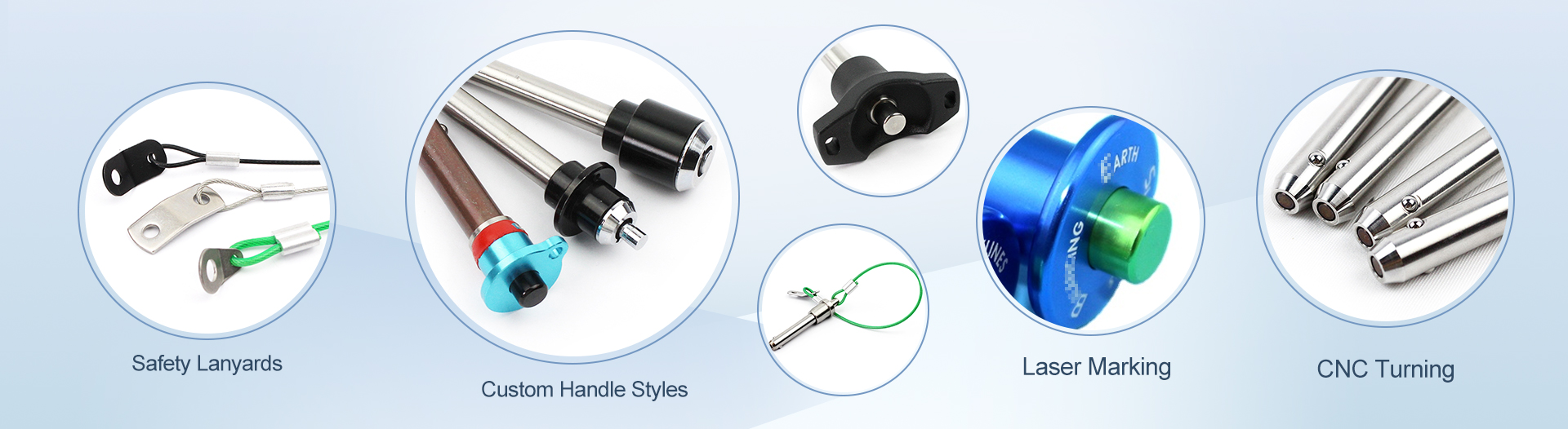
We provide OEM & non-standard customization service as your request:
Custom dimensions: Custom shaft diameter, effective grip length and overall length according to drawings or samples
Material alternative: Replace pin shaft with 304 / 316 stainless steel for better corrosion resistance
Handle upgrade: Swap plastic T-handle to metal grip, ring pull handle or mushroom head button
Surface treatment: Custom coating, passivation and other surface finishes for pin shaft
Laser marking: Engrave material grade, part number or customer logo on the pin body
Locking structure: Optional single-ball or dual-ball locking configuration
Private labeling & custom packaging
Before every installation, verify that the pin diameter, grip length, and hole tolerance conform to DIN specifications. Thoroughly clean the receiving hole using compressed air or a lint-free solvent wipe to remove all metal chips, grit, and residual cutting fluid. Even microscopic contaminants can compromise ball travel and lead to premature spring fatigue. Inspect the pin shaft for nicks or burrs; a clean, dry, and debris-free mating surface is the foundation of repeatable locking performance.
Step 1 — Axial Alignment and Ball Retraction
Grip the pin by its body or molded handle. Pull one of the dual actuating rings fully to retract the locking balls completely inside the shaft. Position the pin coaxially with the target hole—maintaining a true 90° approach angle. Insert the pin with steady, even hand pressure. Avoid any side-loading, rocking motion, or off-axis forcing; angular insertion generates scoring on the shaft surface and can permanently deform the ball-detent mechanism.
Step 2 — Spring-Loaded Engagement and Lock Verification
Once the pin reaches the designated seating depth, release the actuating ring. The internal compression spring drives the locking balls outward into the annular groove of the mating component, establishing a positive, self-securing mechanical interlock. Perform a manual tug test on the assembled joint—the pin should exhibit zero axial play, rotation slack, or lateral shift. For plastic-grip variants, apply controlled hand force only; overtightening can crack the polymer housing without improving lock integrity.
Step 3 — Functional Validation Under Simulated Service Conditions
After installation, conduct a dry-cycle test: retract and extend the balls three to five times to confirm consistent spring rebound and unobstructed ball movement. Where the application involves continuous vibration, reciprocating motion, or dynamic loading, perform a simulated load test at or above the expected operating stress. The pin must maintain full retention force with no partial disengagement, ball hesitation, or handle creep. This validation step is the single most effective safeguard against in-field separation failures.
Why Correct Installation Directly Impacts Service Life
Every Ball Lock Pin relies on a precision-tolerance interface between the spring, balls, and shaft bore. Off-axis insertion, dirty holes, or incomplete ball extension introduces micro-abrasion that compounds over thousands of cycles. Proper vertical alignment, verified hole cleanliness, and confirmed full spring reset preserve the original DIN tolerance envelope—ensuring the pin delivers rated shear strength, repeatable positioning accuracy, and maximum cycle life throughout its service interval.
Standardized Installation Workflow
① | Confirm pin specs & hole dimensional compliance |
② | Clean hole — eliminate all chips, dust, and oil residue |
③ | Pull ring — retract balls — align axially — insert vertically |
④ | Release ring — verify automatic ball lock engagement |
⑤ | Manual tug & rotation check — confirm zero play |
⑥ | Dry-cycle test + simulated vibration/load verification |
A: Press the push button on top of the handle to retract steel balls. Insert the pin shaft through the workpiece hole, then release the button. The balls pop out on the other side to finish locking. Press the button again to retract balls and pull the pin out. No tools are needed.
A: AISI 630 is precipitation hardening stainless steel with higher hardness, strength and anti-deformation performance, ideal for heavy-load and high-frequency use. 304 stainless steel has better corrosion resistance but lower load capacity.
A: The PA polyamide T-handle can continuously work under 80°C. For high-temperature working conditions, we recommend ball lock pins with metal handles to prevent plastic aging.
A: Confirm the pin shaft diameter and effective grip length (the thickness of the workpiece you need to lock). The fixture hole diameter must match the pin shaft diameter. Working load and ambient temperature are also key factors.
Q5: Can you make non-standard ball lock pins? What is the MOQ?
A: Yes, we support custom ball lock pins based on drawings or samples. MOQ varies by specification, and small trial orders are acceptable for most custom projects.


