


Custom Handle Quick Release Ball Pins
PDM
| Quantity: | |
|---|---|
Features of Industrial Ball Lock Pin
PDM Industries manufactures custom ball lock pins for applications where standard safety lock pins cannot satisfy functional requirements. Our flanged push‑button ball lock pins are precision CNC‑machined stainless steel locating fasteners engineered for tool‑free quick positioning, locking and disassembly on jigs, gauges and automation fixturing. Nearly any dimension or feature can be tailored to unique tooling needs; non‑standard shank diameters are available to match existing hole sizes, meet special clearance requirements or integrate into your custom tooling systems. Fitted with an integrated stop flange with relief cutouts and an internal spring‑loaded locking ball actuated by the top push button, the pin delivers repeatable, dependable positioning for frequent changeovers. The built‑in flange works as a depth stop to prevent over‑insertion, perfect for recurring positioning tasks requiring repeated removal and reinstallation.
| Item | Specification |
| Material | 304 Stainless Steel / 316 Stainless Steel |
| Optional Material | Carbon Steel, Alloy Steel |
| Operation Mode | Top push‑button release (press button to retract locking ball) |
| Locking Structure | Spring‑loaded single locking ball; dual‑ball optional |
| Standard Surface Treatment | Passivated (anti‑corrosion, no coating peeling) |
| Optional Surface Treatment | Mirror polishing, hard chrome plating |
| Custom Diameter Range | φ3 mm ~ φ25 mm |
| Effective Engagement Length | Custom per customer drawing |
| Dimensional Tolerance | ±0.02 mm for locating working diameter |
| Operating Temperature | -40°C ~ +200°C |
| Compliance | RoHS compliant |
| Load Standard | Static shear load customized by size & material |
Quick release locking pin are industrial-grade positioning and fast-locking devices that combine high-precision alignment with rapid locking functionality. Featuring a precision-ground shank, the core mechanism is driven by a top-mounted push button that actuates a center spindle, retracting the locking steel balls into radial recesses to achieve instant "press-to-release" positive locking. Available in carbon steel and stainless steel (304/316), the product line includes L-handle, T-handle, button-type, and ring-type variants, with standard diameters ranging from 3/16" to 1" (metric 5–20 mm) and standard grip lengths up to 6" (150 mm). For specialized operating conditions, non-standard custom solutions are also available—including heavy-duty, adjustable, and double-acting models—to fully meet the demands of complex industrial applications
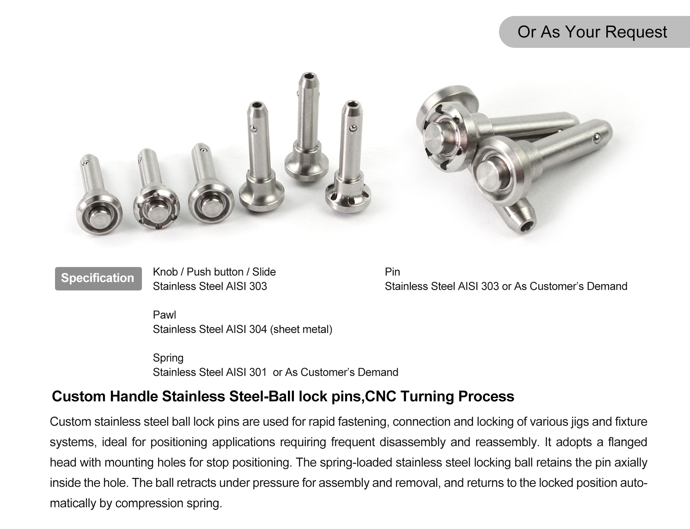
1.Push-Button One-Hand Quick Release
Feature: Requires no auxiliary tools such as wrenches. A single-handed press on the top button retracts the locking balls, enabling fast insertion and extraction.
Advantage: Drastically reduces fixture changeover and equipment setup time, enhances production line flexibility, and lowers manual labor intensity—directly translating into higher operational throughput.
2. Integrated Flange Stop Shoulder with Cutouts
Feature: A physical stop shoulder precisely controls insertion depth, while flange relief cutouts support auxiliary alignment and clamping.
Advantage: Guarantees consistent repeatability and positioning accuracy in every cycle, eliminates the risk of over-insertion, and provides a reliable datum reference for automated assembly and precision machining.
3. Superior Corrosion Resistance
Feature: Standard models use high-quality carbon steel; stainless steel options include 304 for general indoor dry workshops and 316 (available on request) for salt spray, high-pressure washdown, and high-humidity marine environments.
Advantage: Material selection is matched to specific operating severity, effectively extending service life, minimizing corrosion-induced downtime, and reducing long-term maintenance expenditure.
4. One-Piece CNC Machined Body
Feature: Manufactured from a single billet via CNC machining with a precision-ground shank, delivering structural uniformity and high rigidity.
Advantage: Exhibits exceptional resistance to bending deformation under rated static shear loads, ensuring positioning safety during heavy-duty operations and reducing defect rates caused by component deflection.
5. Stable Spring-Ball Locking Assembly
Feature: Automatically engages a positive lock once the button is released; the internal spring mechanism is robust and vibration-resistant.
Advantage: Prevents accidental disengagement caused by operational vibration, adding a critical layer of safety redundancy while the long service-life design reduces spare parts procurement frequency.
6. Thread-Free Locking Design
Feature: Replaces traditional threaded connections with radial ball locking, eliminating thread galling, seizing, and slow manual tightening.
Advantage: Ensures smooth, reliable operation even in high-frequency insertion/extraction scenarios, eliminating thread-related failure modes and improving overall maintenance efficiency.
Notes:Ball Lock Quick Release Pin Specifications & Customization
Standard Specifications: Diameters from 3/16" to 1" (5–20 mm); grip lengths up to 6" (150 mm). Handle styles: L-type, T-type, button-type, ring-type.
Quick Release Pin Ball Locking Pin (Specific dimensions can be customized according to the drawings or consulted with the manufacturer)
| Nominal Diameter | Shank Dia. d1 (Min / Max) | Shank Dia. d2 (Min / Max) | l2 (Grip Length) | Head Outer Dia. D | Head Height l4 | Total Length l3 | Neck Dia. d4 d4 | Center Hole d3 |
| 5 | 4.92 / 4.96 | 5.54 | 6 (±13) | 20.6 | 16 | 23.4 | 11.9 | 5.8 |
| 6 | 5.92 / 5.96 | 6.99 | 7 (±13) | 20.6 | 16 | 23.4 | 11.9 | 5.8 |
| 8 | 7.92 / 7.96 | 9.42 | 8 (±13) | 20.6 | 16 | 23.4 | 11.9 | 5.8 |
| 10 | 9.92 / 9.96 | 11.86 | 9 (±13) | 25.4 | 17.8 | 25.7 | 14.2 | 7.4 |
| 12 | 11.92 / 11.96 | 14.45 | 10 (±13) | 34.7 | 21.6 | 32.3 | 18.3 | 10.7 |
| 16 | 15.92 / 15.96 | 19 | 14 (±13) | 44.5 | 27.9 | 41.9 | 23.9 | 13.7 |
Please refer to the size specifications below for reference:
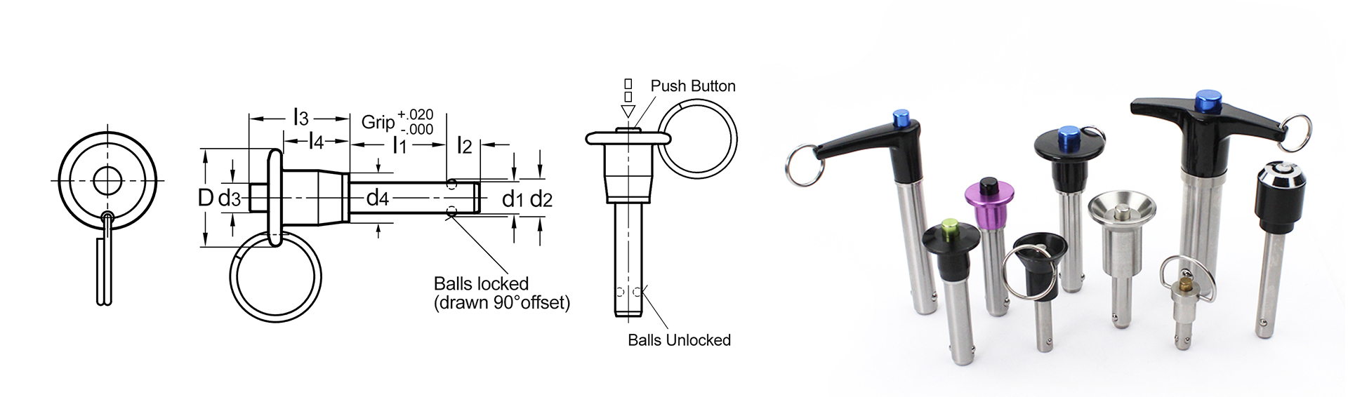
| Custom Length Ball Lock Pin-Metric | |||||||||
| Nominal Diameter | d1 Min. | d1 Max. | d2 ±13 | l2 +.000/-.76 | l3 | d4 | l4 | d3 | D |
| 5 | 4.92 | 4.96 | 5.54 | 6 | 23.4 | 11.9 | 16 | 5.8 | 20.6 |
| 6 | 5.92 | 5.96 | 6.99 | 7 | 23.4 | 11.9 | 16 | 5.8 | 20.6 |
| 8 | 7.92 | 7.96 | 9.42 | 8 | 23.4 | 11.9 | 16 | 5.8 | 20.6 |
| 10 | 9.92 | 9.96 | 11.86 | 9 | 25.7 | 14.2 | 17.8 | 7.4 | 25.4 |
| 12 | 11.92 | 11.96 | 14.45 | 10 | 32.3 | 18.3 | 21.6 | 10.7 | 34.7 |
| 16 | 15.92 | 15.96 | 19 | 14 | 41.9 | 23.9 | 27.9 | 13.7 | 44.5 |
| Custom Length Ball Lock Pin-Inch | |||||||
| Diameter d1 | d2 | I2 | d3 | d4 | D | I3 | I4 |
| 3/16 | 0.22 | 0.26 | 1/4 | 1/2 | 13/16 | 7/8 | 5/8 |
| 1/4 | 0.289 | 0.39 | 1/4 | 1/2 | 13/16 | 7/8 | 5/8 |
| 5/16 | 0.375 | 0.33 | 1/4 | 1/2 | 13/16 | 29/32 | 5/8 |
| 3/8 | 0.44 | 0.365 | 5/16 | 19/32 | 1-1/8 | 1-3/16 | 13/16 |
| 7/16 | 0.509 | 0.38 | 5/16 | 19/32 | 1-1/8 | 1-3/16 | 13/16 |
| 1/2 | 0.594 | 0.46 | 15/32 | 3/4 | 1-3/8 | 1-13/32 | 1 |
| 9/16 | 0.666 | 0.51 | 15/32 | 3/4 | 1-3/8 | 1-1/2 | 1 |
| 5/8 | 0.75 | 0.58 | 9/16 | 15/16 | 1-3/4 | 1-5/8 | 1-1-16 |
| 3/4 | 0.887 | 0.67 | 5/8 | 15/16 | 1-3/4 | 1-19/32 | 1-1/16 |
| 7/8 | 1.046 | 0.76 | 3/4 | 1-1/4 | 2-1/8 | 2/1/8 | 1-15/32 |
| 1 | 1.209 | 0.89 | 3/4 | 1-1/4 | 2-1/8 | 2-1/8 | 1-15/32 |
The Core Function of Custom Quick Release Pin Manufacturer
1. Positive Locking: Spring-Loaded Spindle for Secure, Self-Locking Retention
Inside the quick lock pin gym, a spring-loaded internal spindle continuously pushes the steel balls outward so that they protrude slightly beyond the pin shank. The balls then seat firmly behind a mating receiver hole, groove, or counterbore, creating reliable axial and radial locking force. Compared with friction-dependent spring pins, ball lock pins provide positive, non-loosening positioning — making them ideal for quick location and load-bearing connections in high-vibration applications.
2. Quick Release: Push to Retract the Balls, Tool-Free Installation and Removal in Seconds
To install or remove the pin, simply depress the actuator button (or pull the spindle). This moves an internal relief that releases the outward thrust on the balls, allowing them to retract fully inside the shank — so the pin can be inserted or removed instantly, with no tools required. This quick-release feature makes ball lock pins the preferred choice for automated equipment changeovers, jig and fixture quick change, and any application involving frequent assembly and disassembly.
3. 360° Radial Retention: Even Load Distribution for Superior Shear and Pull-Out Resistance
The steel balls distribute the holding force evenly around the entire circumference of the mating hole, rather than relying on a single-direction slot or groove like a slot pin. This 360° radial retention design delivers excellent shear strength and pull-out resistance, maintaining stable positioning accuracy and connection rigidity even under heavy loads, impact, and high-frequency vibration.
Handle & Actuation Options to Fit Every Installation Space
Threaded Ends — for connecting pneumatic cylinders, robotic linkages, or custom actuation rods, enabling remote or automated actuation.
Knurled or Hex Heads — for easy tool engagement and anti-rotation alignment in tight spaces.
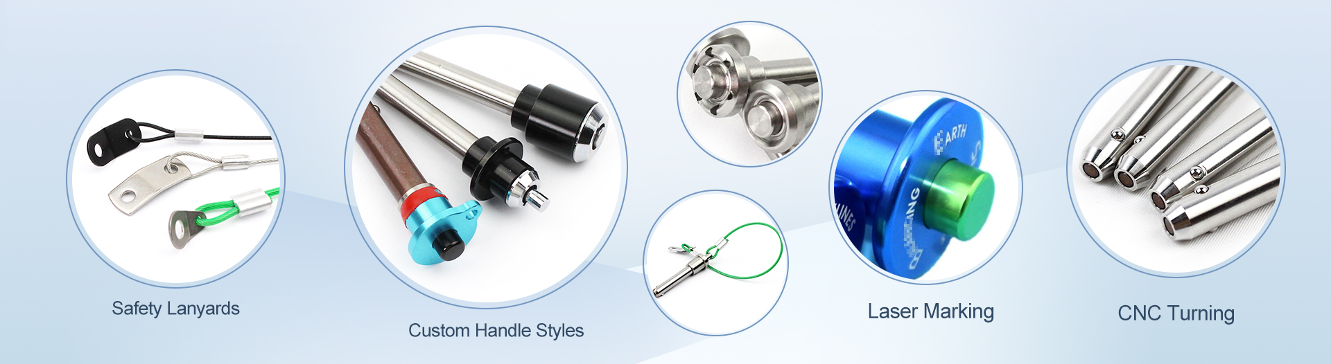
Special Profiles — T-handle, L-handle, ring, and low-profile styles to accommodate gloved operation, high-leverage pulling, and limited-clearance installations.
Application of Heavy duty ball lock pin:
Automotive checking fixtures & machining jigs: For precise part locating, clamping and dimensional inspection during CNC machining and quality validation processes.
Industrial automation tooling, robot end‑effector fixtures: Used for reliable workpiece fixation in robotic pick-and-place, automated assembly and handling workflows.
Conveyor line positioning stops & quick‑change stations: Accurately register workpieces and support fast product changeovers on continuous production conveyor lines.
Mold and die quick replacement systems: Facilitate fast mold swapping to cut downtime for stamping, forming and molding production.
Aerospace assembly tooling: High-precision locating for aerospace structural components with stringent tolerance and safety requirements.
Medical equipment positioning fixtures: Ideal for assembly and inspection of medical parts, leveraging stainless steel’s corrosion resistance and clean performance.
Test bench and laboratory positioning assemblies: Secure test specimens for repeated calibration, performance testing and R&D trials.
Custom pin diameter, effective engagement length and overall length
✅ Custom flange outer diameter, flange thickness, quantity & layout of flange cutouts
✅ Material switching: 304 / 316 stainless steel, carbon steel, alloy steel
✅ Custom surface finish as required
✅ Dual‑locking‑ball upgrade for higher shear load and anti‑vibration demand
✅ Custom load design according to actual working conditions
✅ Support 2D/3D drawing or sample reverse development
Step‑by‑Step Installation & Removal Guide- Ball lock pin diameter 8mm
Align the ball lock pin with pre‑machined locating holes on your fixture or workpiece. Never force the pin into misaligned holes to avoid scratching the pin and hole bore.
Fully depress the central top button to retract the locking ball completely into the pin body. Partial pressing leads to jamming and fast wear of the ball.
Slide the pin in smoothly until the flange shoulder sits flush against the workpiece surface, which ensures accurate, repeatable locating depth.
Release the push button. The internal spring pushes the locking ball outward to lock the pin securely. Confirm the ball is fully engaged before applying working load.
For removal: Press the top button all the way down to retract the ball, then pull the pin straight along the pin axis. Angled pulling will damage the locking ball.
⚠️ Important Reminder:
Do NOT apply lateral side load, strike or hammer the pin while the locking ball is retracted. This will permanently damage the internal spring and locking assembly.
Q1: How do I select the right pin diameter and effective length?
A: The pin diameter should match your locating hole size. The effective engagement length equals the thickness of the stacked plates to be positioned. Send your workpiece drawing for our engineer’s recommendation.
Q2: What is the difference between 304 SS and 316 SS versions?
A: 304 stainless steel offers good corrosion resistance for normal dry indoor workshops. 316 stainless steel with molybdenum delivers outstanding salt‑spray and chemical resistance for washdown and coastal working environments.
Q3: Can you supply dual‑ball flanged ball lock pins for heavy‑load use?
A: Yes. Dual‑ball locking structure is available upon request, which improves shear capacity and anti‑vibration performance for heavy‑duty positioning.
Q4: What is the cycle life of these High precision Stainless Steel ball lock pin?
A: Standard 304/316 pins can achieve tens of thousands of lock‑unlock cycles under rated load and clean working conditions. The actual service life depends on load, dust and chemical exposure.
Q5: Can you develop non‑standard pins from my drawings?
A: Yes. Submit your 2D/3D drawings, load requirements and surface treatment demands. Our engineering team will review feasibility and issue a formal quotation.


